
Automatic Card Dealer
Carnegie Mellon University
Senior Capstone, Electromechanical Systems Design
Spring 2020
Best Prototype Award
For my capstone, I worked with 3 other mechanical engineering students to create a device called the Automatic Card Dealer, which aims to eliminate the role of the dealer by automatically distributing cards according to a specific card game that is chosen by the players. The players communicate with the device via Amazon Echo Dot Alexa smart speaker— this is how they choose the game, and the dealer determines the location of the individuals. Blackjack and Poker are the two available games thus flipping the cards is a necessary feature. Users are able to make commands ‘hit’ and ‘stay’ by using hand motions that are detected by ultrasonic sensors. Due to COVID-19, my team and I had to work remotely and were unable to complete the project according to our original plan, which consisted of a fully working physical prototype.
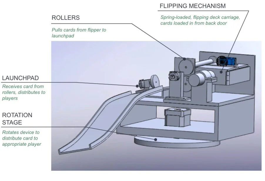
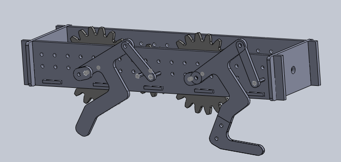
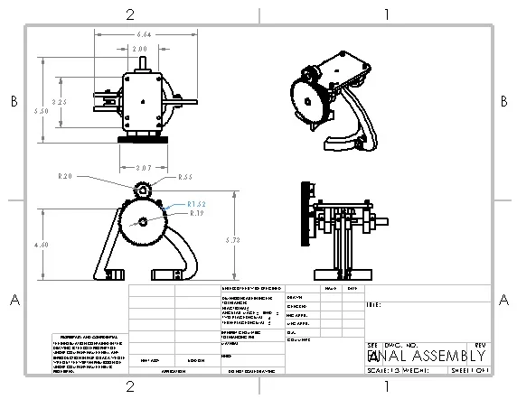
Full Assembly CAD
Launch Pad Subassembly
In addition to the CAD, we created prototypes of the subsystems: the launch pad and the deck module, and a basic user interaction framework involving Alexa. The launch pad involved a motor that kicked a single card from the device to the user.
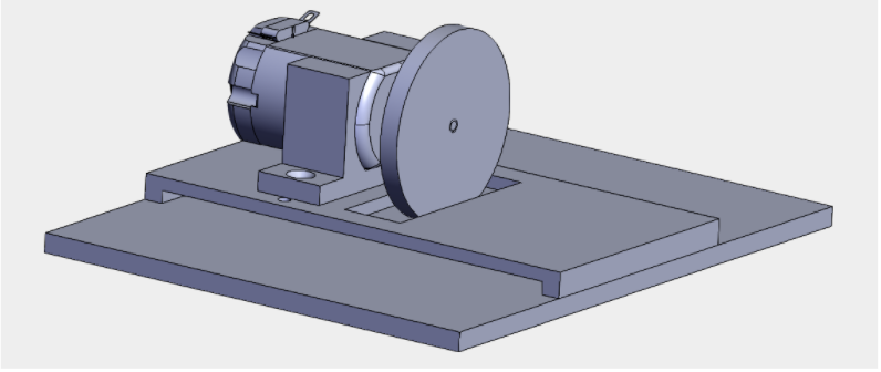
First Prototype of Launch Pad CAD
The launch pad physical prototype was improved by printing multiple wheels for the launch pad in order to increase the consistency of the wheel-card contact. Testing the accuracy of the launch pad was conducted by measuring the location of the resulting position of the card. The final prototype was much more accurate compared to the first and second since the horizontal distance between the initial and final positions was minimized. Also, the coefficient of friction of front of card to back of card, front of card to tape, and back of card to tape were determined. These values helped determine if the friction was a factor that significantly affected the system’s design and how much force must be applied between interacting modules to achieve substantial interaction.
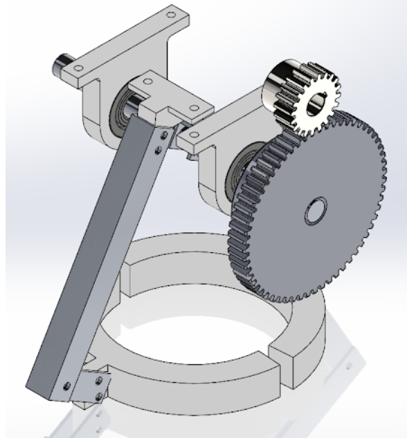
Deck Module Subassembly
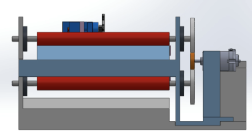
The deck module was able to flip the entire deck to 180 degrees to distribute a card both orientations— face up or down. The first prototype physical assembly is shown below. The second prototype CAD integrated rollers to ensure successful transfer of a single card from the deck module to the launch pad.
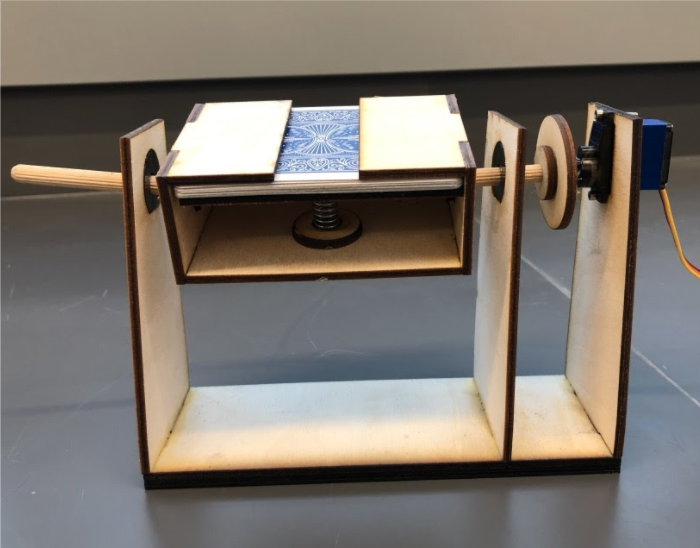
First Prototype of Deck Module
For the final prototype, we planned to use a DC motor with encoder for the deck rotation to increase accuracy. During tests, the angle of the motor was read from the output of the encoder on the laptop via Arduino. The main drawback of this test setup was that we fail to attach any inertial component (e.g. a real deck) or exert any load to the shaft of the motor. During the test, we let the motor rotate between 0 degrees and 180 degrees repeatedly and recorded the rotation time and the position error of each rotation. Through these tests, the PID parameters Kp, Ki, and Kd were determined. The position error of the motor was found to be 0.1360 degrees. Alexa-Arduino interaction as well as using ultrasonic sensors to detect location of players were both determined to be a reliable source of communication.
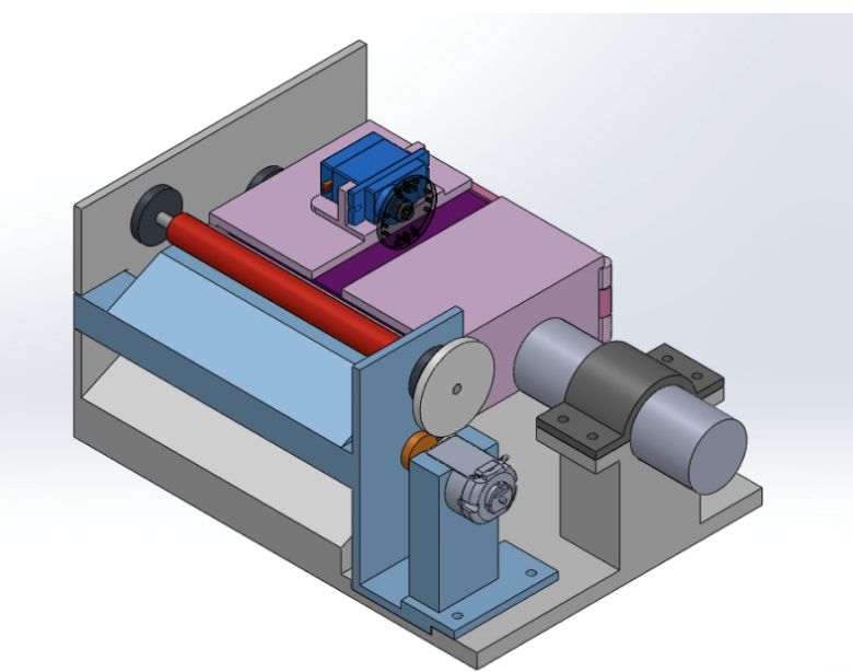
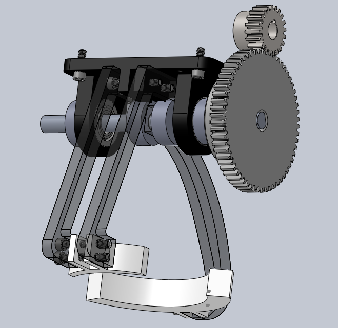
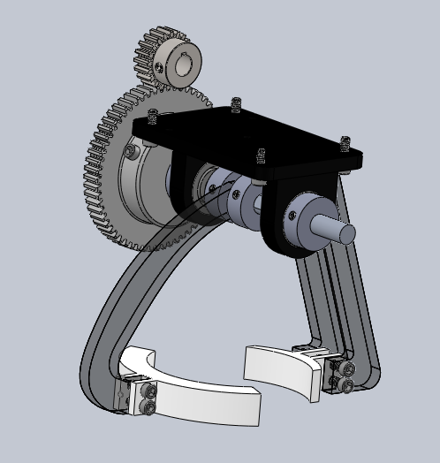
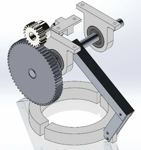
Second Prototype of Deck Module (view 1)
Second Prototype of Deck Module (view 2)
User Interaction
The user interface component allowed players to communicate with Alexa to choose select and play the game. By using the Arduino IoT + Alexa, ultra sonic sensor and servo, the Automatic Card Dealer was likely to detect the location of players. The ultrasonic sensor can detect large objects as well as hand motions for ‘hit’ or ‘stay.’ The device sits on a platform that is connected to a servo— this allows the assembly to rotate to accurately distribute the cards.
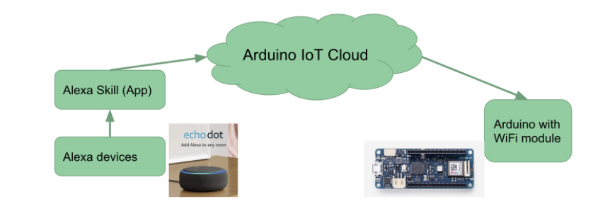
System Structure of Arduino IoT
Conclusion
If this project was to be continued, more rigorous testing would be conducted that would take into account more specific parameters such as how the size of the deck affects the rotation of the deck module. The entire system would be constructed and modifications would be made accordingly. One of the goals of the project was to have the device replace a live card dealer in casinos, so it must have the same speed or be faster than a person. If the product is unable to match the performance of a person, then there is no reason for the device to be used in a casino. Additionally, we would like the Automatic Card Dealer to be able to deal other games besides blackjack and poker.
Bidirectional Carriage
Interview design challenge
January 2019
Scope of Problem:
I was tasked to design a carriage that can move forward, neutral and in reverse via conveyor belt. This involved manual changing between modes with no tools required. I was also given a few specifications for the conveyor belt, which I also had to design.
My Solution:
My solution involves a carriage with wheels that allow the chassis to rest on upper level of the conveyor belt. The chassis has four arms— two attached to the upper level and two attached to the lower level of belt.
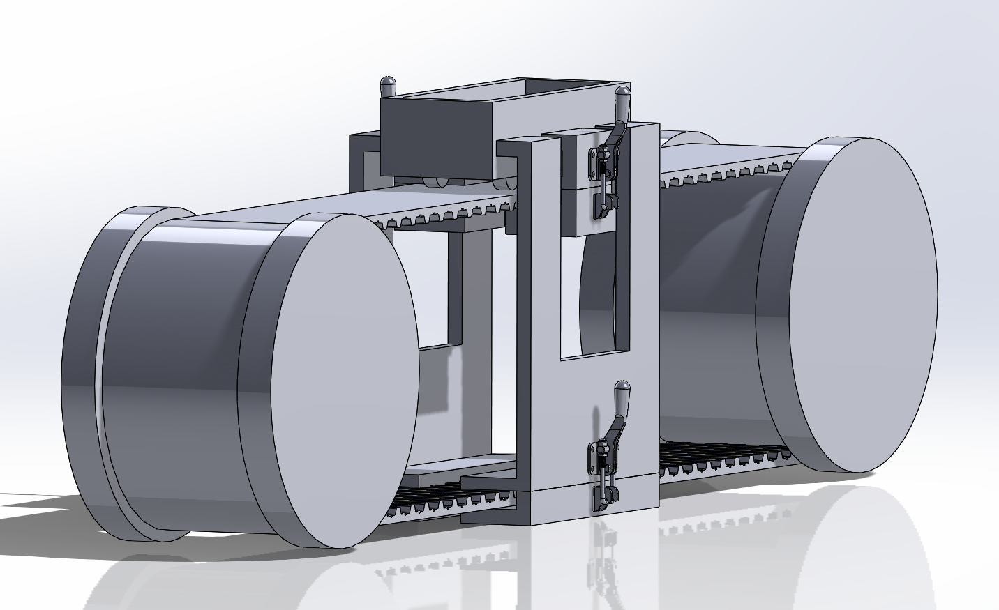
Full assembly of carriage and conveyor belt
Inspiration:
My main source of inspiration for the carriage design was from the mechanics of a drill press. It consists of levers A and B that allow two modules to move in various directions. This consists of a lever that locks the modules.
How It Works:
Assume that the conveyor belt moves clockwise. When Levers A, the upper level arms, are clamped and Levers B, the lower level arms, are not engaged, the carriage moves forward. When the Levers B are clamped and Levers A are not engaged, the carriage moves in reverse. When all arms are not in contact with the belt, the carriage is in neutral; a person can move the carriage in any direction with the force of his hand.
Check out the full design challenge and solution in the link below:
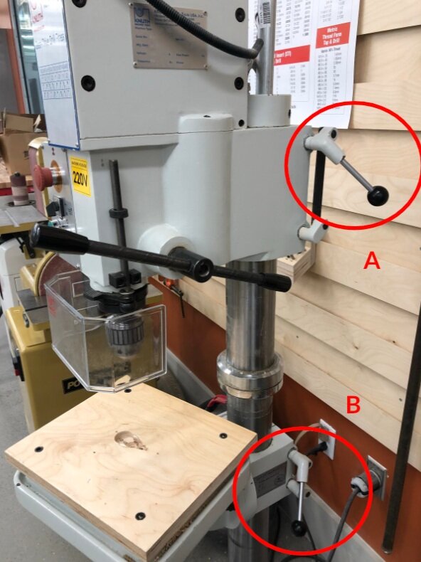
Drill Press
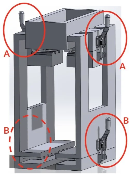
Carriage with labeled levers
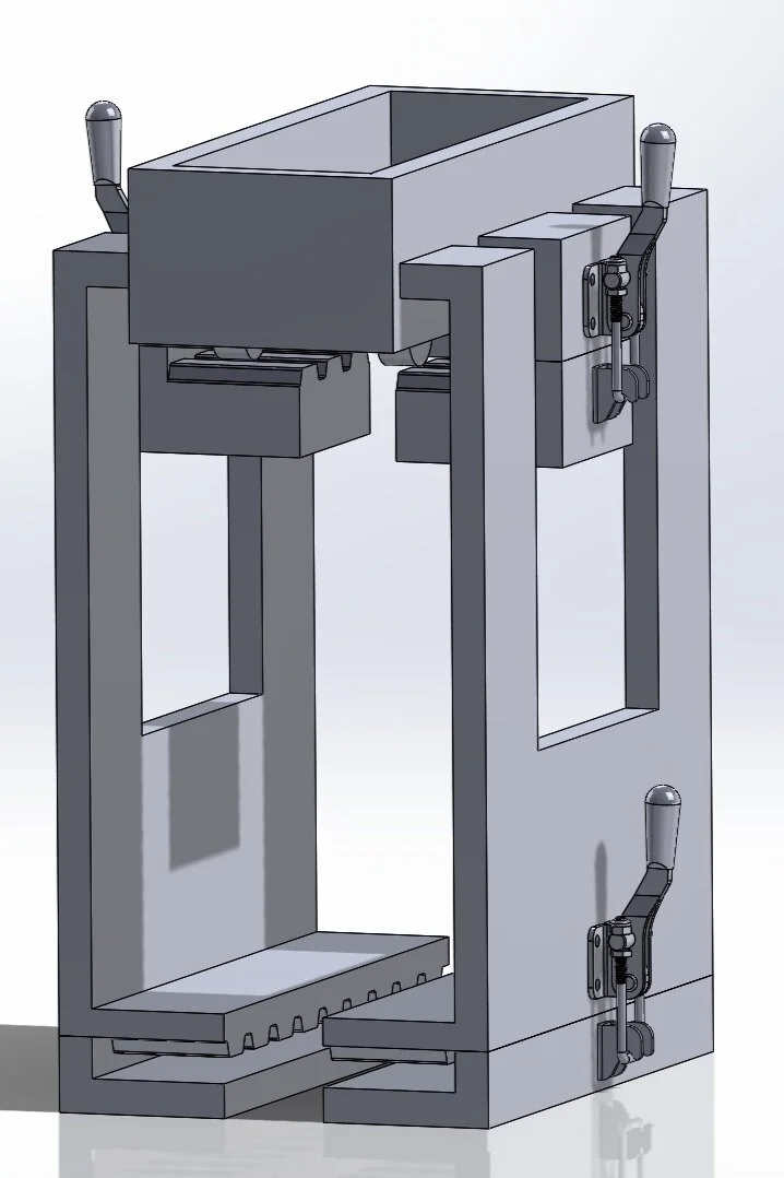
Carriage in isometric view
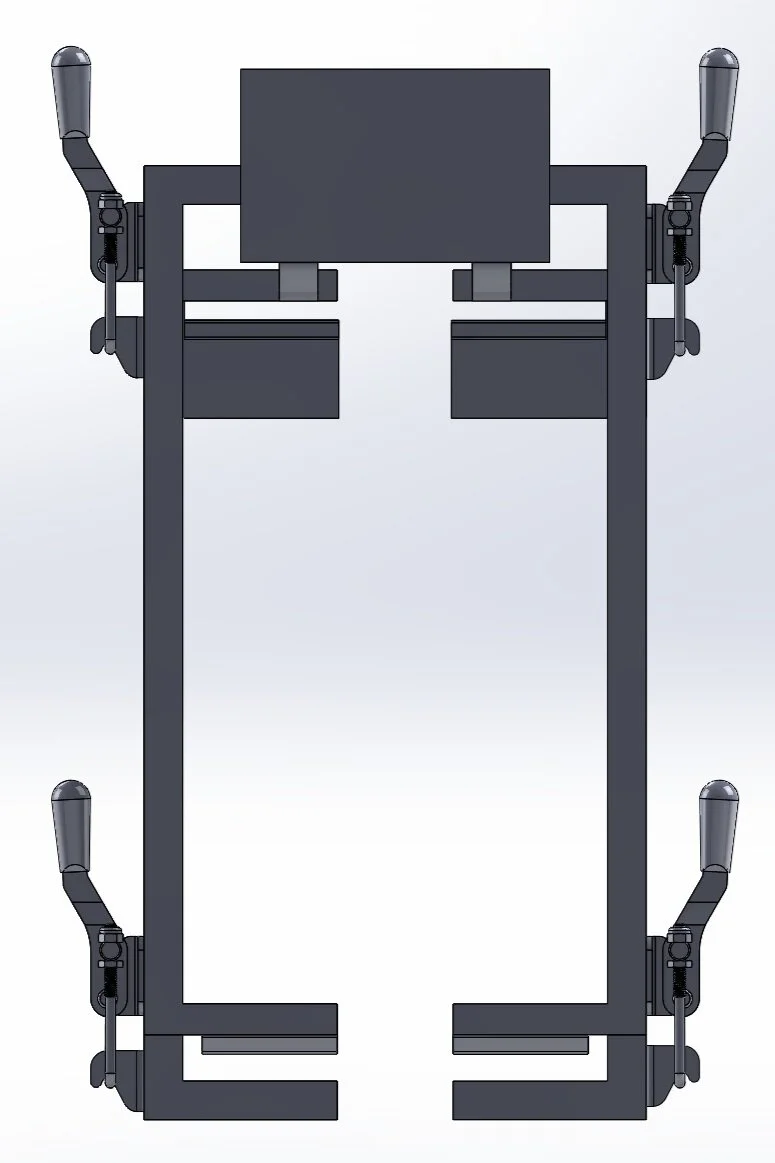
Carriage in front view
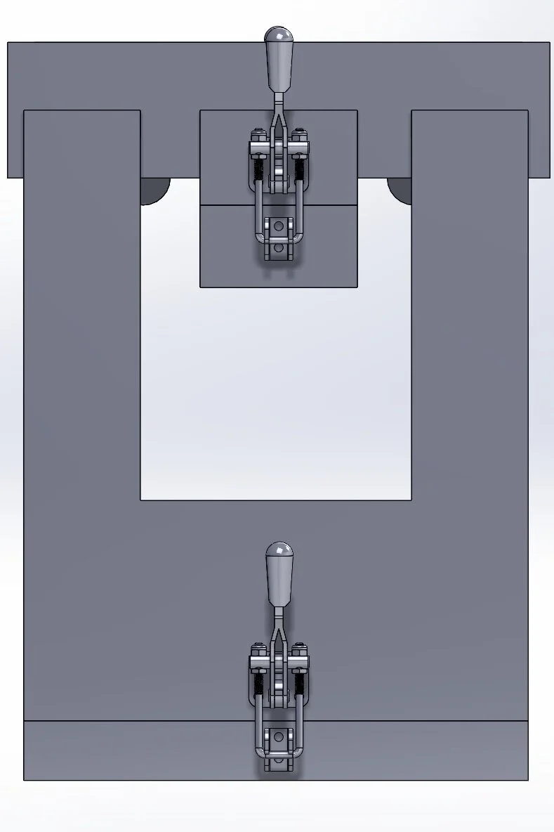
Carriage in side view
Upright Vacuum Exploration
SharkNinja, Shark Advanced Development Team
August 2019 - December 2019
As a mechanical design engineering co-op, I was tasked with creating a design from two of our current upright vacuums that would allow for a more efficient air pathway. This would allow the vacuum to use less power to achieve a higher amount of suction and cleaning. In order to determine where the most constriction occurred in an airway, I pressure taped different sections of each vacuum and determined the flow rate. By using computer-aided design on Creo and Solidworks, I was able to use 3D printed parts and released vacuum parts to construct a make-shift, working vacuum.
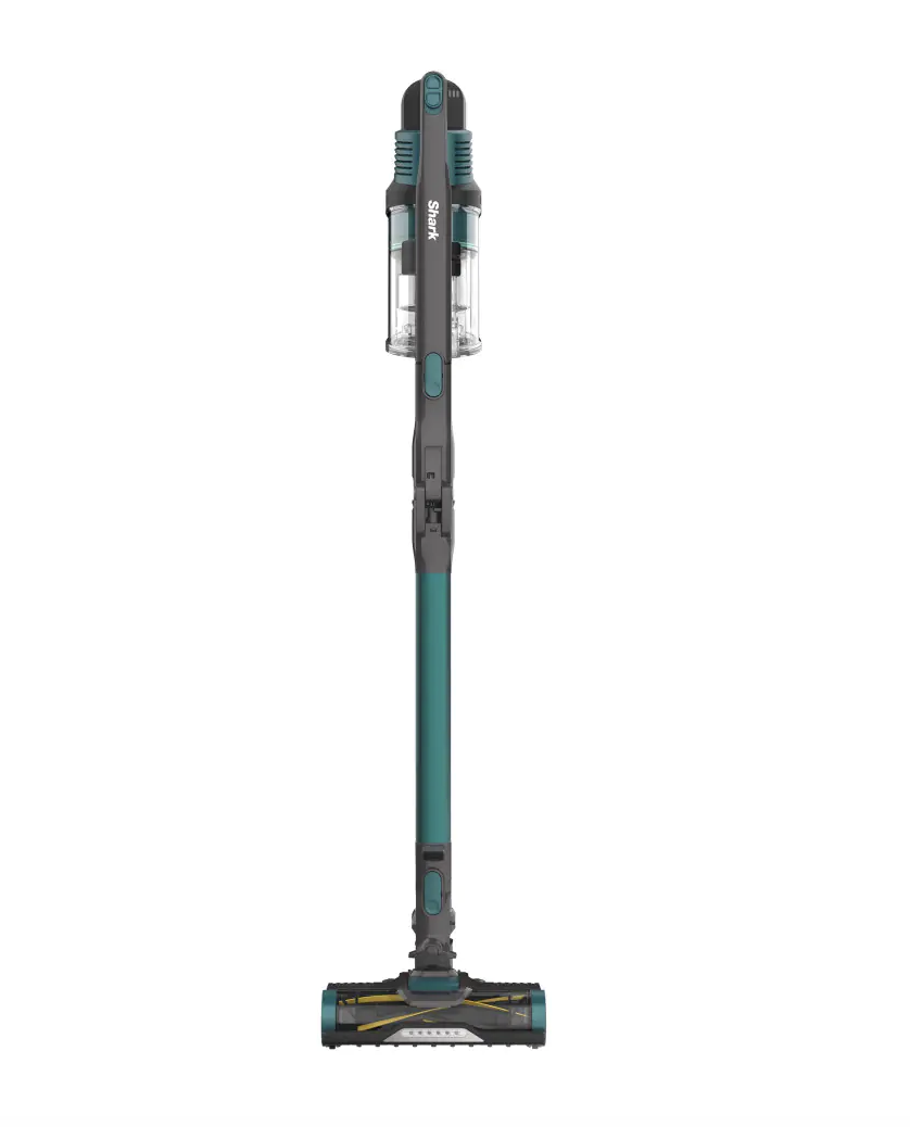
Shark Rocket Pro Cordless Stick Vacuum with Self-Cleaning Brushroll

Shark DuoClean Cordless Upright Vacuum Cleaner with Powered Lift-Away IC160UK
JUMP Battery Pack
Uber, Battery Team
May 2019 - August 2019
As a mechanical engineering intern on the Uber Elevate Battery Team, I worked on the battery pack enclosure by engaging in computer-aided design using SolidWorks, design validation tests, leak testing, etc. The mechanical design involved working with manufacturers and suppliers on EVTs and DVTs by using geometric dimensioning & tolerancing to create drawings for the factory. I also worked on creating the next potential battery pack by editing the current pack’s CAD and corresponding with suppliers for advice for how to proceed.
In order to ensure the pack would be able to withstand the pressure of being submerged 1 meter underwater, I worked on determining an ideal stabilization time for a pressure decay test using MatLab and Microsoft Excel. Our goal was to minimize the cycle time to speed up the assembly line. By running various tests, I was able to analyze the slope of the curve and identify when the pressure versus time curve became about linear.
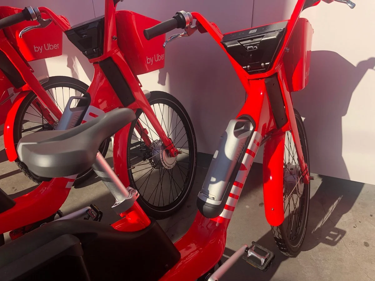
JUMP bike with swappable battery pack
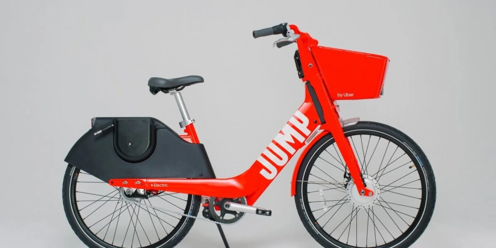
JUMP Bike
Automated Manicure Machine
Carnegie Mellon University
Gadgetry: Sensors, Actuators and Processors
Fall 2018
Along with one other mechanical engineer, as a term project for our class, we created an automated manicure machine that consisted of: a nail filer, a fan and a nail painter. The project was completed by using multiple Arduinos.
The nail filer was made from a DC motor with a 3D printed attachment and sandpaper. It was activated by pressing a pushbutton.
The fan’s speed was determined by a proximity sensor and activated by a push button.
The nail painter’s arm was a four bar linkage and used a stepper motor to drive it. The arm was activated by pressing a button, and then it would only start painting once the user’s finger was on the stand. We used a photo sensor to detect the user’s finger.
The chassis and other hardware components were constructed using laser cut acrylic.
If you would like to see a demo of each module, the links are below!
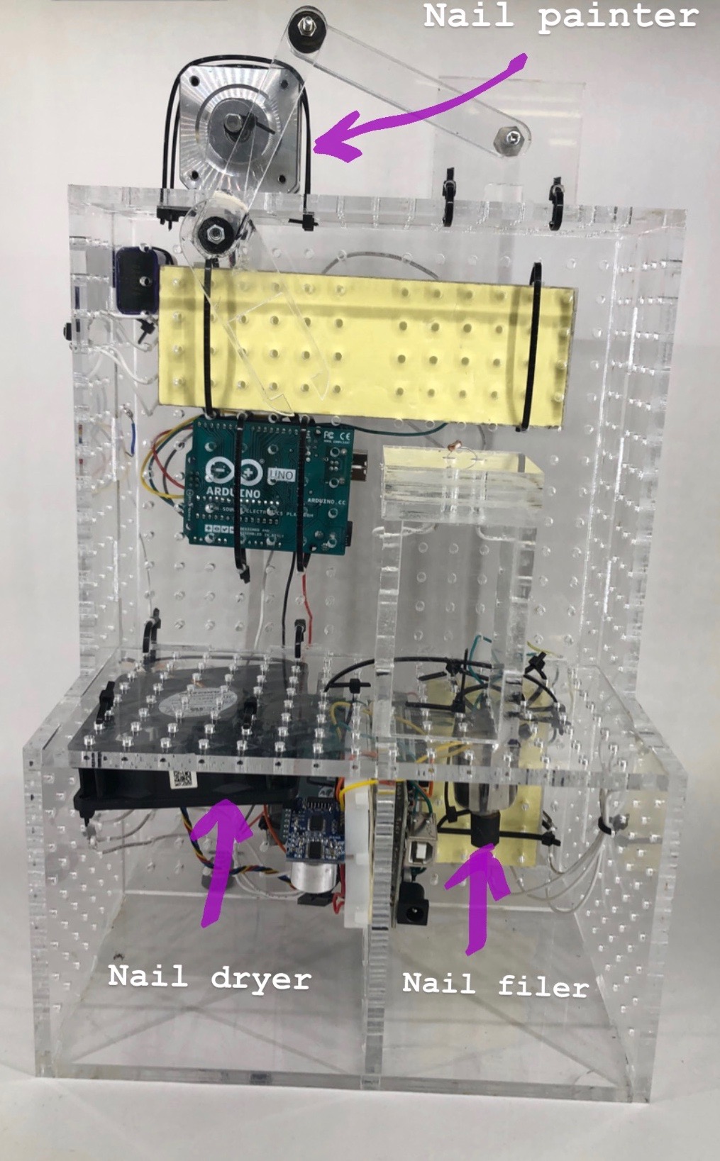
The Final Assembly: Front View
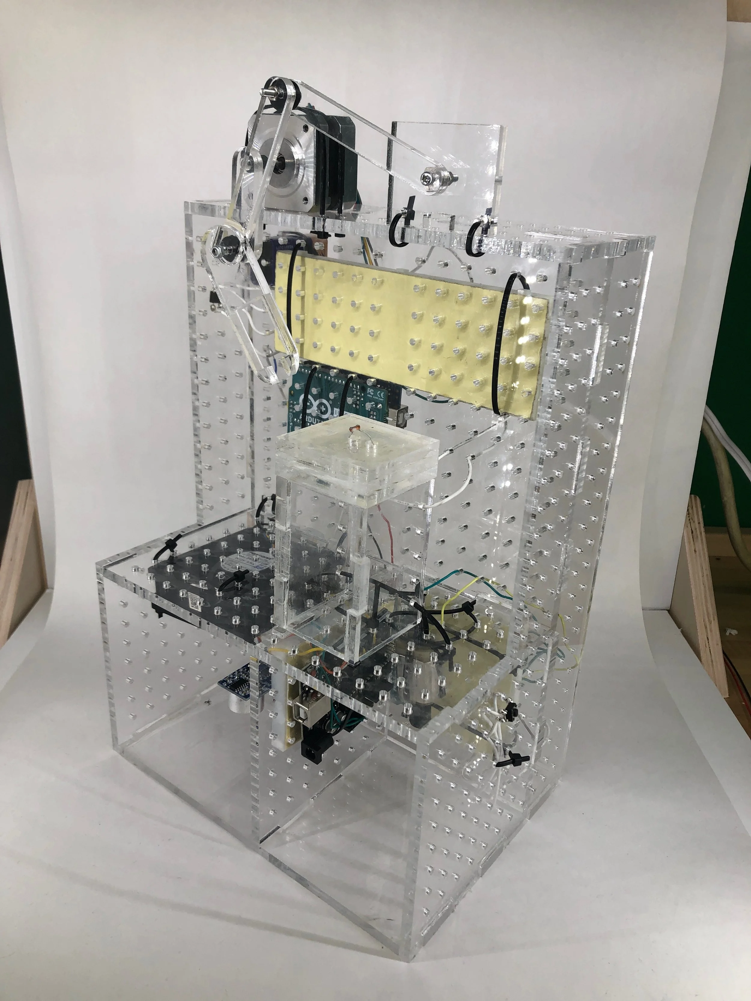
The Final Assembly: Isometric View
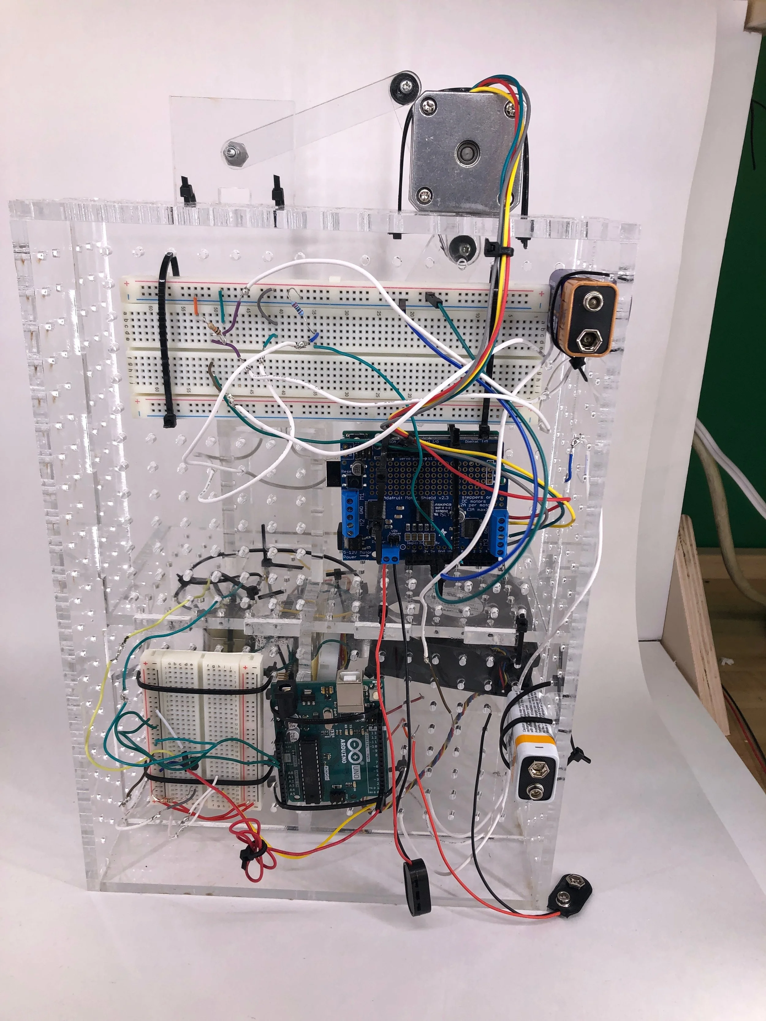
The Final Assembly: Back View
Rudolph the Walking Robot
Carnegie Mellon University
Engineering Design 1: Methods and Skills
Fall 2018
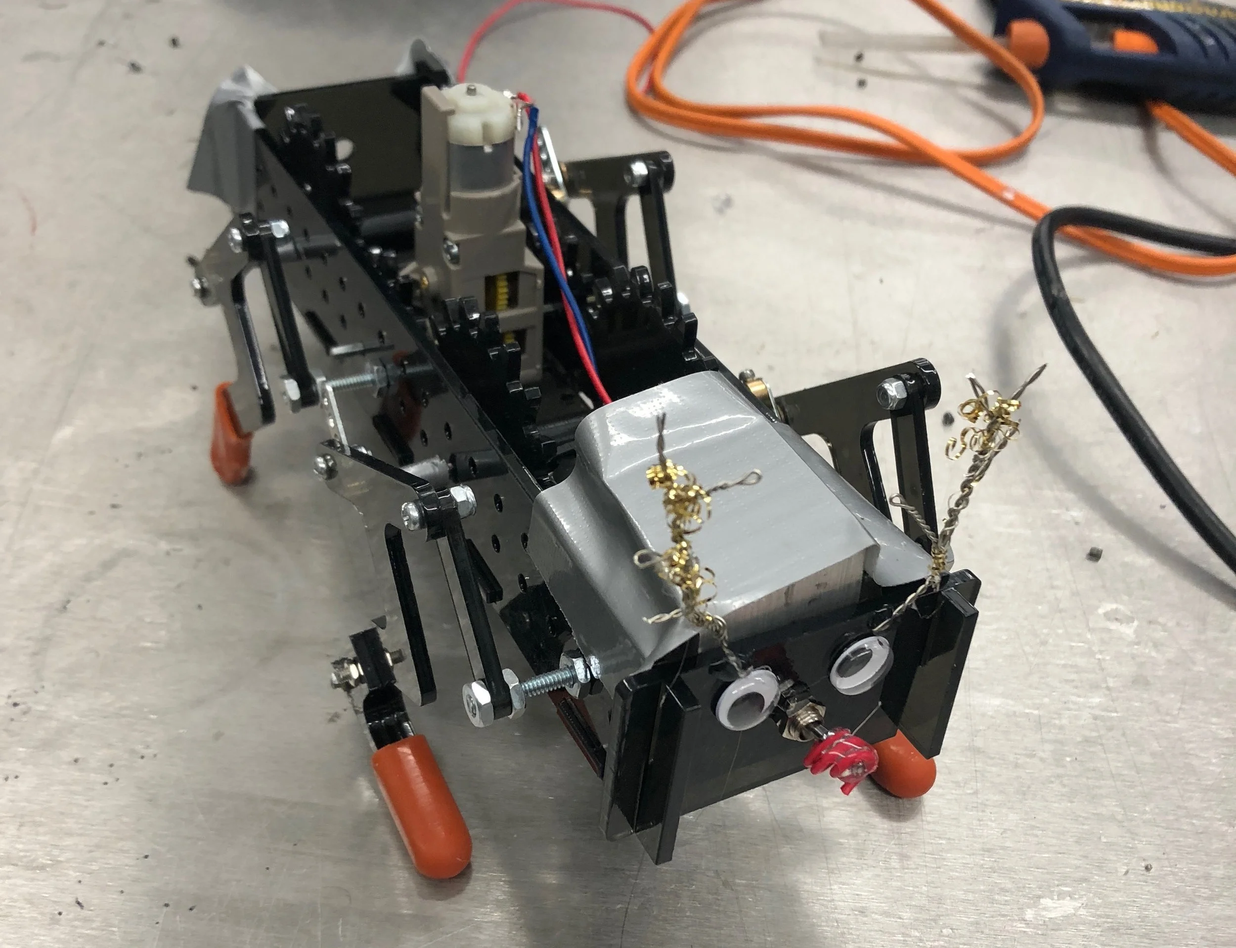
The Final Assembly
With three other mechanical engineers, we were tasked to create a walking robot from a customizable gearbox that was a part of a kit every group in the class was given. One of the requirements was to incorporate four bar linkages for the legs. The main goal of the project was to complete a course that consisted of a smooth course with multiple hills and rocks that lined the edges of the pathway. This course was about 12 ft long. We were graded on speed, how much of the course was completed and style.
The design process consisted of calculating the required gear specifications, and configuring the customizable motor. This was determined by the weight of the robot, the angle of the hills and the geometry of the legs. After, we made a few iterations for the legs. Starting off with pegs, we were able to determine the best shape that would allow the robot to climb the hills while also being able to move forward; for some iterations, the robot was able to travel on a flat plane, but was unsuccessful at climbing hills.
This project was challenging since we had to make sure the robot could walk up hills successfully while maintaining a straight trajectory. The robot was off balanced so we had to attach a weight to the rear of the chassis to make the robot complete the course successfully.
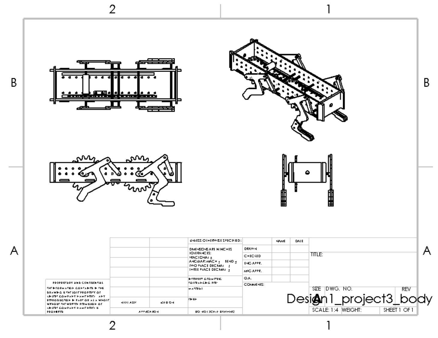
CAD Drawings of Final Assembly
CAD of Final Assembly
Gripper
Carnegie Mellon University
Engineering Design 1: Methods and Skills
Fall 2018
The final assembly
With four other mechanical engineers, we were tasked to create a gripper that could pick up an object, swing it multiple times from 180 degrees and place the object in its original location. The arms opened and closed due to the direction a motor was ran; this motor was attached to the gear of the gripper. Our object was a weighted reusable water bottle top
Our final assembly had plastic gears and spacers. The base and hands were 3D printed and the arms were laser cut.
Our first iteration had plastic gears, 3D printed base and hands and the arms were machined aluminum.
The final assemly
The final assembly CAD drawings
The first iteration
The first iteration
Astronaut’s Coat Hanger
Carnegie Mellon University
Engineering design 1: Methods and Skills
Fall 2018
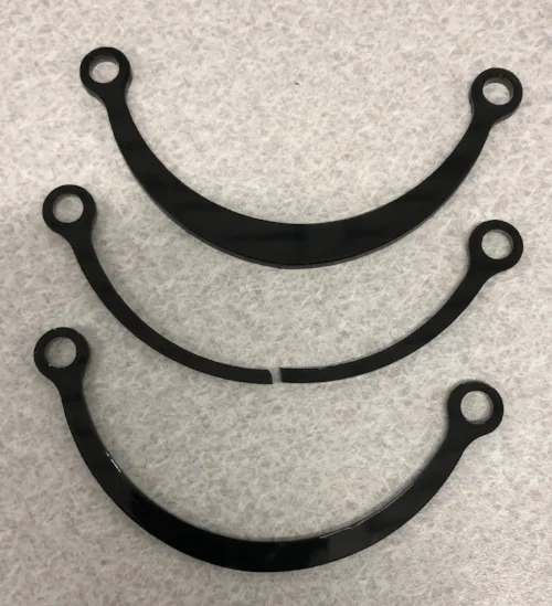
I was tasked to laser cut an acrylic bracket that could hold 25 lb for 10 seconds. This involved design analysis and manufacturing iterations to decrease the weight of the bracket.
I created my bracket by using a shape that distributed the forces along the part. Then I determined where and which stress was the largest and set the factor of safety to 1. From working backwards and using SolidWorks FEA analysis, I found the thickness of my bracket and changed the value from trial and error testing.
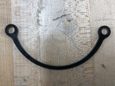
My final manufactured bracket
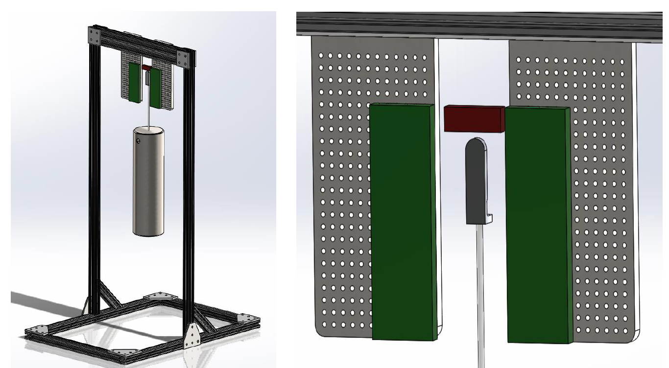
Design set up: bracket cannot cross red zones and cannot be pinned in green zones
My last three iterations
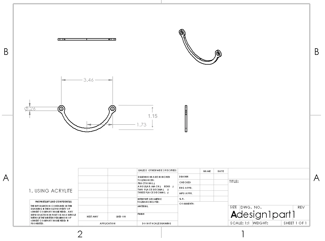
The SolidWorks drawing of my final part
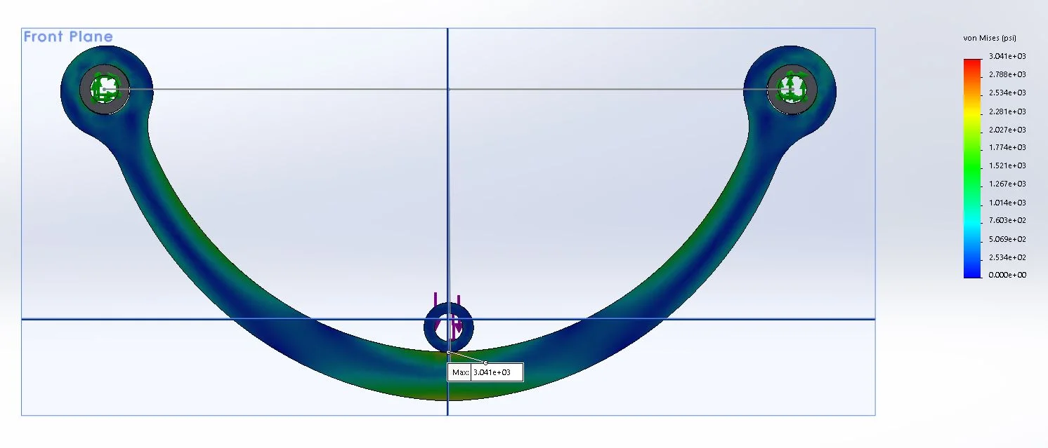
The FEA stress distribution of my final part
Shake n' Wake
Carnegie Mellon university's build18
Spring 2018
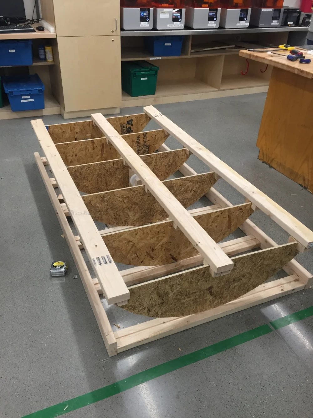
Through CMU's Build18 event, two other mechanical engineering students and I created a bed that rocks a person back and forth in order to wake them up. There is a motor underneath the middle of the bed and a belt that is attached to the sides of the frame in order to move the bed side to side. An alarm clock and Arduino were used for indicating when the motor would start. We constructed the frame ourselves.
3D printer
Carnegie Mellon university
Advanced Fabrication Techniques for HCI 05-435
spring 2018
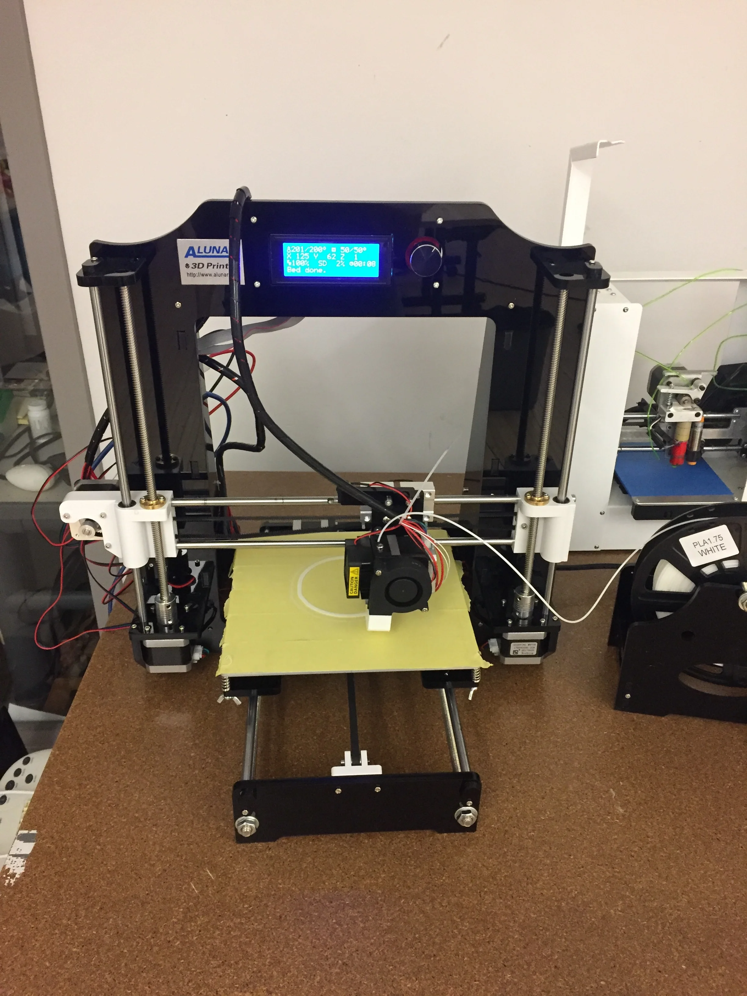
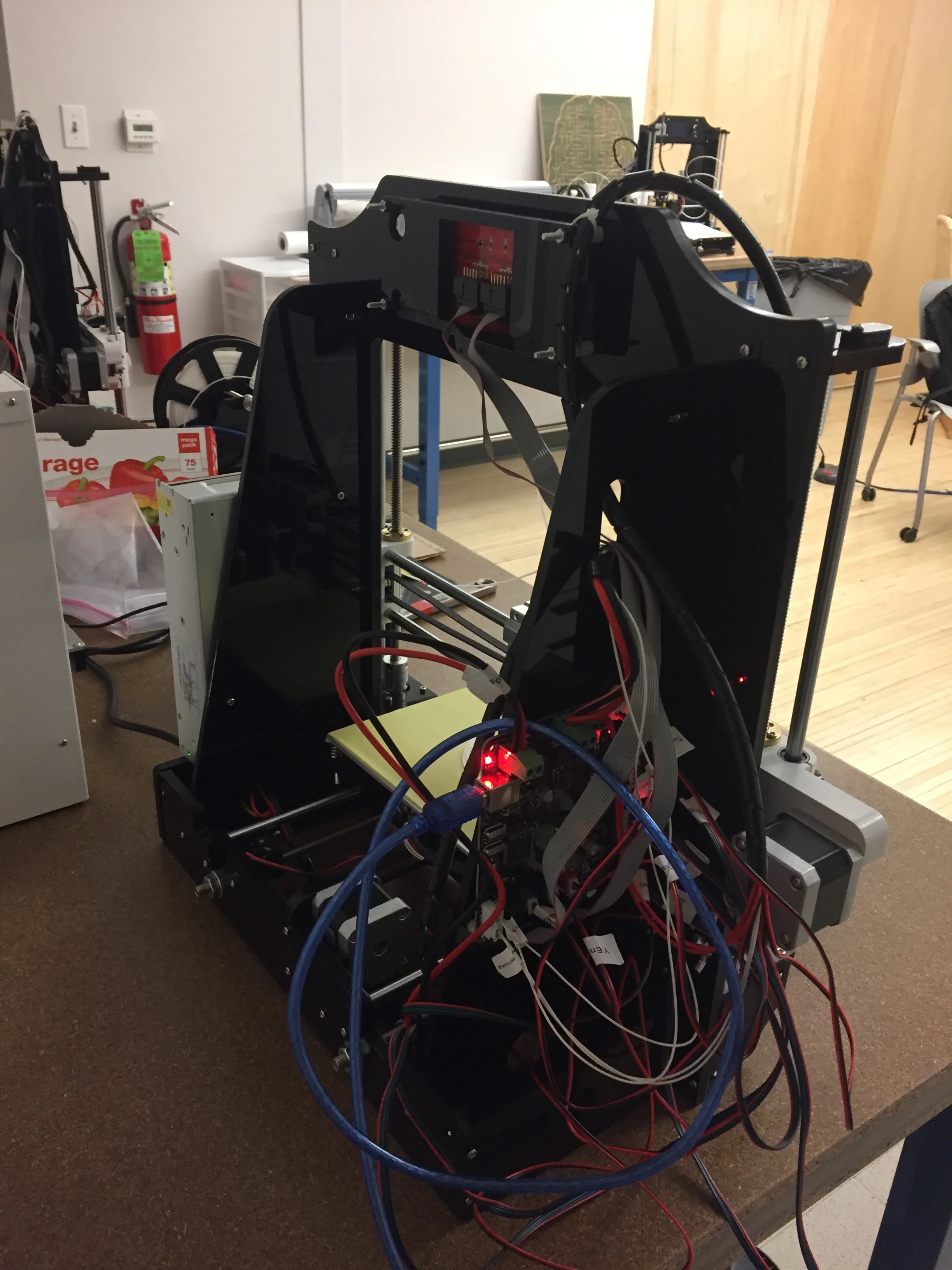
I built an Alunar 3D printer from scratch by following instructions provided from a kit. After, I CADed and printed by projects for the class. It took about 8-10 hours to successfully build the printer.
crane project
carnegie mellon university
Stress Analysis 24-262
spring 2018
In a group with two other students, we created a crane that lifted a 1 pound weight up by 2 inches. The crane had to go through a hole in the wall without touching it. The materials involved were aluminum strips, a servo motor, nuts and washers.
Check out my website to learn more about the project: showard18.wixsite.com/mysite
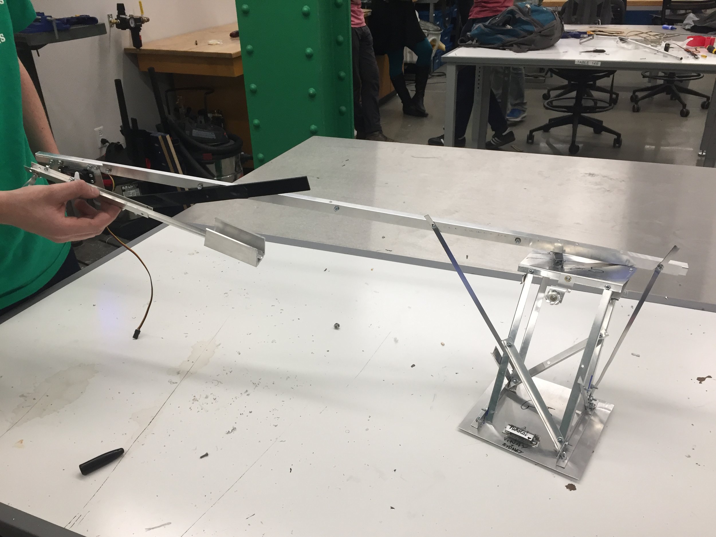
Crane Model
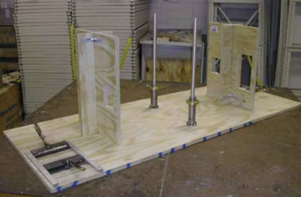
Demostration Field
”PAINT 112” GAME
carnegie mellon university
introduction to programming 15-112
spring 2017
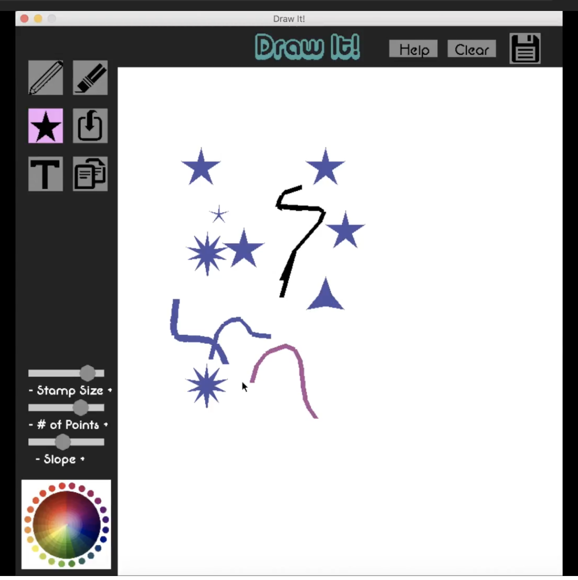
For my term project for the Introduction to Programming class at CMU, I created a game on Python using Pygame that allowed users to draw on a canvas with a variety of tools. Some of the modules included: a paintbrush, eraser, shapes, uploading pictures, etc. Users can also save the art they create.
Park Bench
carnegie mellon university
Advanced fabrication techniques for HCI 05-435
spring 2018
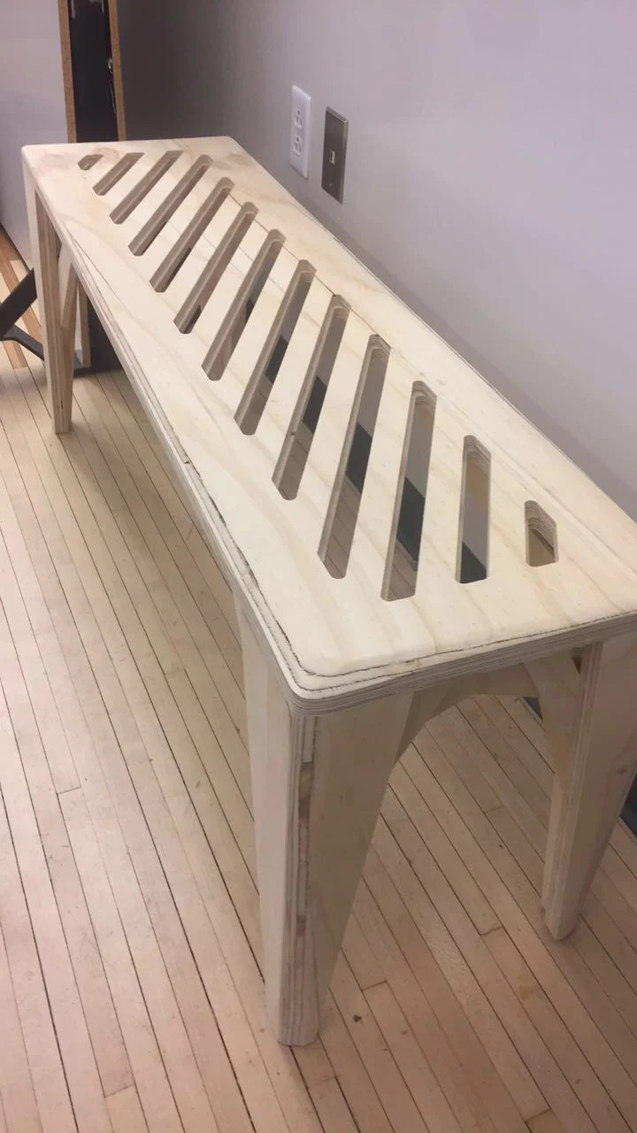
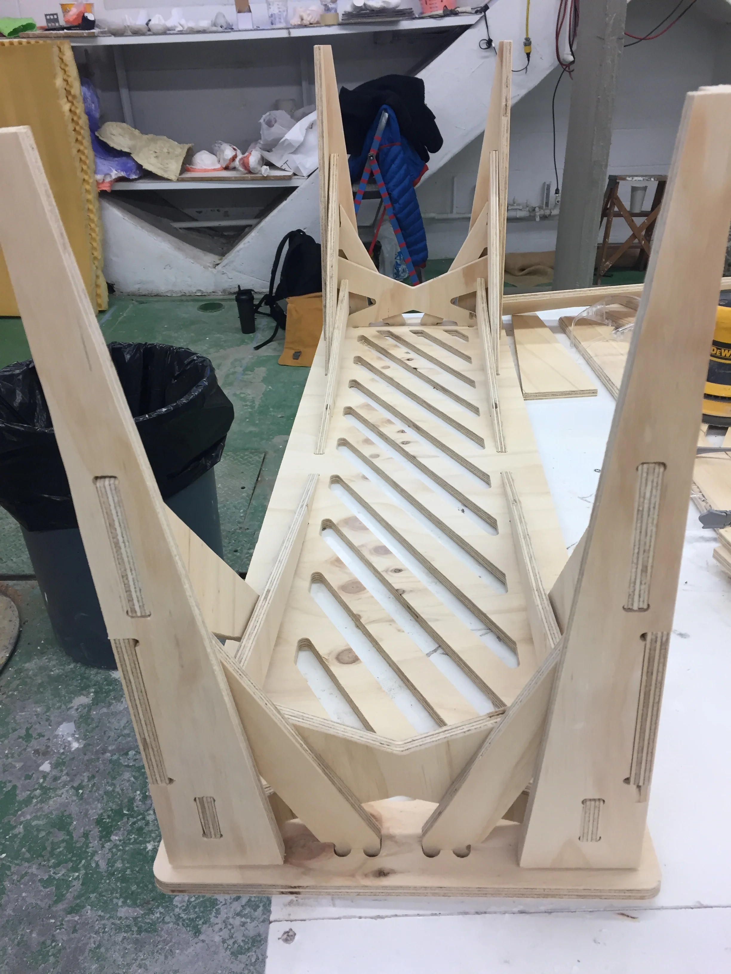
Along with two other students, we designed and fabricated a bench that was able to hold two people. We used SolidWorks to plan it and a CNC machine to cut the wood. The goal of the project to use joinery techniques to create a piece of furniture.
diagnosing shoulder mris
Carnegie mellon university
Integrated Design Innovation Group
september 2018 - december 2018
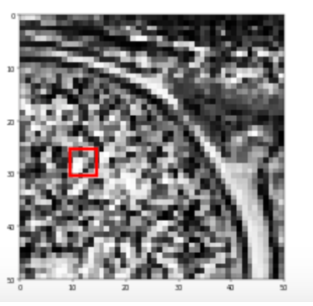
I am working with a neural network that classifies a shoulder as unhealthy or healthy by analyzing MRI images. In order to increase the confidence doctors have in the neural network's ability to diagnose the images, I am creating an interactive program. This module indicates the critical area in the image that was involved in the classification.
MOUSE TRAP CAR PROJECT
carnegie mellon university
introduction to mechanical engineering 24-101
fall 2017
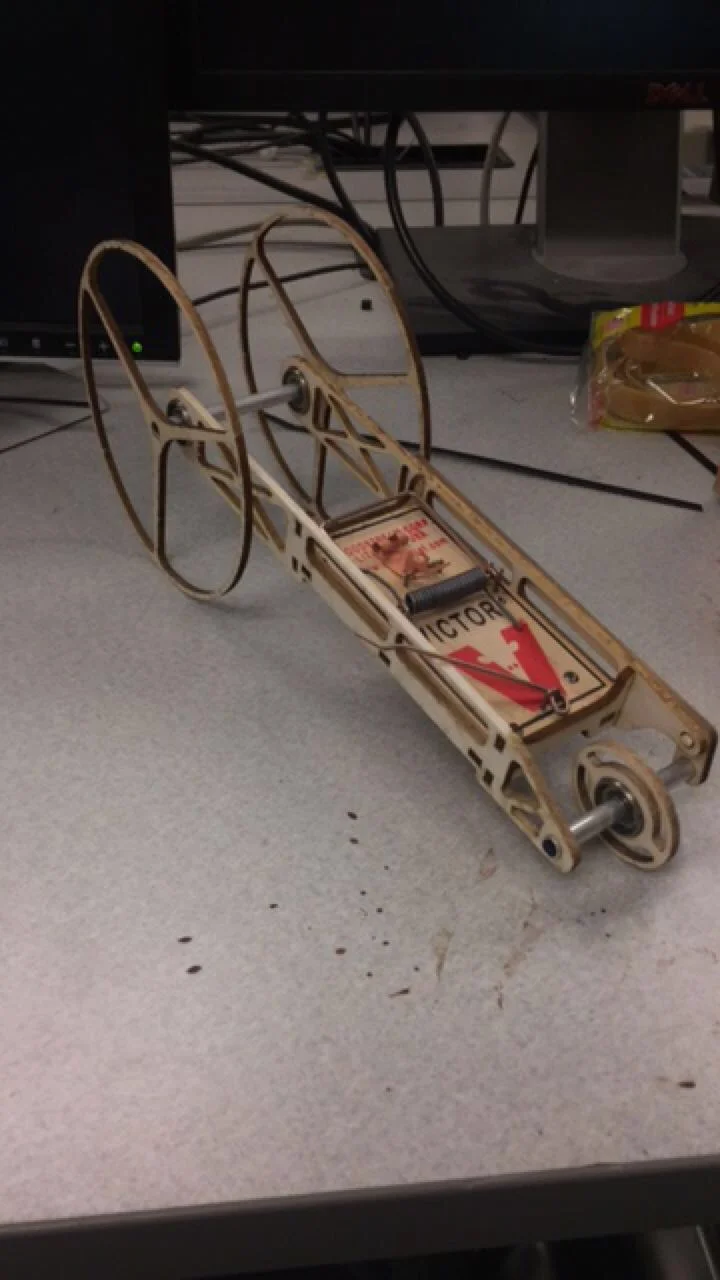
One of three engineers to create a vehicle that could travel to a checkpoint and backward to the starting point autonomously. The car was laser cut balsa wood.
DESIGN DECISIONS NEURAL NETWORK
carnegie mellon university
INTEGRATED DESIGN INNOVATION GROUP
September 2017 - may 2017
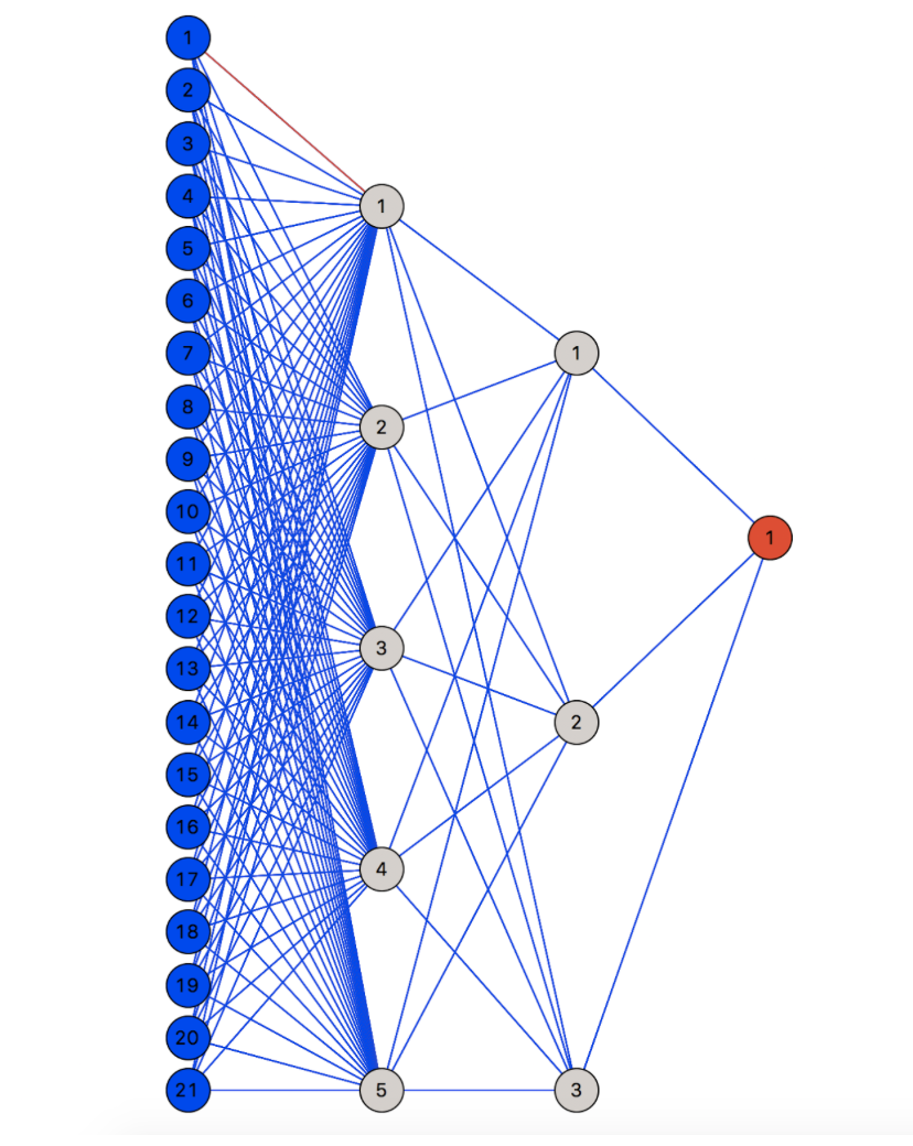
I created a neural network using Anaconda’s sklearn module that could predict the design decisions of a student making and altering a bridge. In order to visualize the neural network, I created an image that displays the layers of the program.